FRED Sr. II Dual-Arm Help & Support
MENU ☰
Learn how to get the most out of your FRED Sr. II Dual-Arm and troubleshoot common problems.
See our help topics and support videos below, and download the FRED Sr. II Dual-Arm product guide and owner's manual.
How to..
Unpack Unit
- Inspect carton for any possible damage during transit and remove packing material.
- Use forklifts or trucks to move.
- Remove packing material.
- Do not tip or invert while handling.
- You’ll find the item serial number, model and electrical ratings located on the nameplate. Write down information on the provided Maintenance Record found in the owner’s manual.
Installation
Tools required:
- 7/16 Socket or Wrench
- 9/16 Socket or Wrench
- Torque Wrench
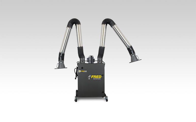
Mobile Model/Arm-to-Blower Direct Installation
- Unpack capture arm, hood, and base.
- Attach swivel base to mounting plate:
- Mount Swivel Base to Mount Plate.
- Tighten all Bolts (8) with Washers (8).
- Torque each bolt to 23 N m
- Attach capture arm to swivel base:
- Insert Spacers (3) between Capture Arm Mounting Bracket.
- Thread Bolts (3) with Washers (3) through Mounting Bracket and Spacers.
- Mount Capture Arm Assembly to Swivel Base.
- Thread Washers (3) and Locking Nuts (3) to Bolts (3).
- Tighten all Bolts (3) to Locking Nuts (3).
- Torque each bolt to 40 N m
- Install flex hose:
- Mount Flex Hose to Swivel Base and Capture Arm.
- Tighten Both Hose Clamps.
Wall/Ceiling Mounted Model Installation
- Wall mount bracket standard assembly:
- Mount Swivel Base to Remote Mount Bracket.
- Tighten all Bolts (8) with Washers (8)
- Torque each bolt to 23 N m
- Attach capture arm to swivel base:
- Mount Swivel Base to Remote Mount Bracket.
- Tighten all Bolts (8) with Washers (8).
- Torque each bolt to 23 N m
- Attach J-Bracket to Arm Swivel:
- Mount J-Bracket to Swivel Base.
- Tighten all Bolts (8) with Washers (8) and Nuts (3).
- Torque each bolt to 34 N m
- Attach Capture Arm to Swivel Base. (J-Bracket):
- Insert J-Bracket between Capture Arm Mounting Bracket.
- Thread Bolts (3) with Washers (3) through Mounting Bracket and J-Bracket.
- Thread Washers (3) and Locking Nuts (3) to Bolts (3).
- Tighten all Bolts (3) to Locking Nuts (3).
- Install flex hose:
- Mount Flex Hose to Swivel Base and capture Arm.
- Tighten Both Hose Clamps.
Before you use your unit, you’ll want to perform a function test to verify it’s in working order.
- Confirm correct Voltage and Amperes
- Close front and back doors.
- Turn the power switch to “On”.
- Look to confirm that the unit is level and stable. Verify nothing is obstructing extraction path.
- Listen closely to the motor and suction sound of the unit. Are they within the expected noise limits?
- Place hand on top of the unit and feel for any unexpected vibration. Place your hand in front of the intake surface to confirm the expected levels of suction.
Weekly Inspection- Empty Dust Drawer
- Remove dust drawer and deposit accumulated particulate in appropriate waste container. (Dispose according to local regulations.)
Filter Replacement
- As required.
Yearly Inspection
- Clean labels and exterior surfaces.
- Capture Arm: Check for tears in flex hoses and fitting of hose clamps.
- Cabinet: Look for loose wiring.
- ICS-360 Function Test:
- Open Cabinet Door (keep open).
- Remove Filter.
- Turn unit ON then OFF.
- Observe if ICS-360 cycle initiates (normal delay of 30 seconds).
- Observe if air nozzle passes the complete range (bottom-to-top) of acme shaft.
Troubleshooting
- Confirm correct voltage. Make sure the remote switch has been plugged into the correct voltage.
- Check fuses. Make sure the fuses are intact and there hasn’t been a loss of power phase.
- Check motor rotation. Confirm the correct rotation using the indication arrow located on the motor. If the unit fails to turn on, the unit’s motor could be in reverse rotation and spinning incorrectly. An electrician is required to address the problem.
- If the problem continues, contact Diversitech support for assistance.
- Confirm correct voltage. Make sure the transformer (Primary and Secondary) has been plugged into the correct voltage.
- Check the nozzle tip. The nozzle tip should contain 2 magnets. For the cleaning mechanism to function properly, the magnets need to be maintained in place at all times.
- If the problem continues, contact Diversitech support for assistance.
- Check the filter latch. Readjust the filter latch as needed to keep the filter sealed into place.
- Verify the condition of the filter gasket. Check the filter gasket for bypass, damage tears or rips.
- Check the inside of the cleaning mechanism. If the mechanism is dirty on the inside, maintenance is required.
- If the problem continues, contact Diversitech support for assistance.